超细微粉磨粉机
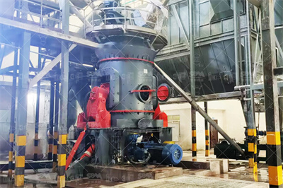
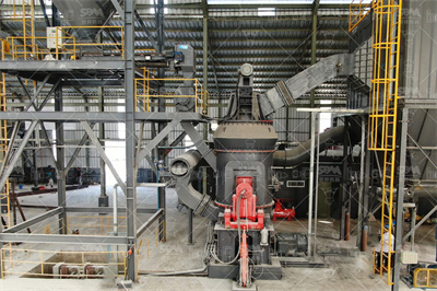
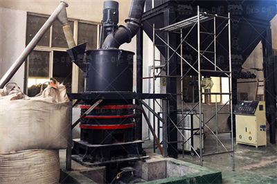
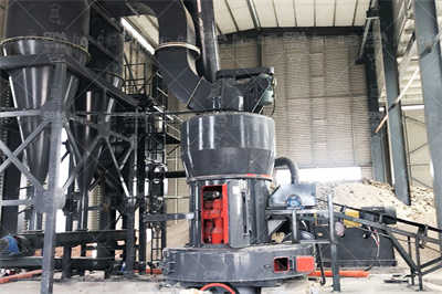
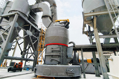
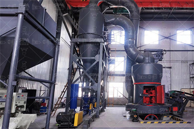
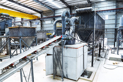
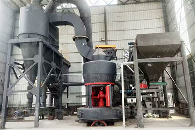
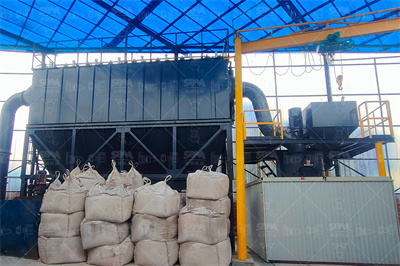
超细微粉磨粉机是一种细粉及超细粉的加工设备,此微粉磨主要适用于中、低硬度,湿度小于6%,莫氏硬度在9级以下的非易燃易爆的非金属物料。它是经过20多次的试验和改进,为超细粉的生产而研发制造的新型磨粉机,…
目录![]() +86 180 3780 8511We Hava More 35 Years Of Expeiences
+86 180 3780 8511We Hava More 35 Years Of Expeiences


超细微粉磨粉机是一种细粉及超细粉的加工设备,此微粉磨主要适用于中、低硬度,湿度小于6%,莫氏硬度在9级以下的非易燃易爆的非金属物料。它是经过20多次的试验和改进,为超细粉的生产而研发制造的新型磨粉机,…

我们公司专业生产大、中型雷蒙磨粉机,拥有22年磨粉经验,科菲达已经成为中国领先的磨粉机制造商和供应商。 R系列雷蒙磨粉机是经过我们的专家优化升级改造,具有低损耗、投资小、环保、占地面积小等优点,它比传…

MTW系列欧式磨粉机是我公司新近推出具有国际先进技术水平,拥有多项自主专利技术产权的最新粉磨设备—MTW系列欧式磨粉机,以悬辊磨粉机9518为基础,采用欧洲先进制造技术,它能满足客户对产品粒度、性能可…

获得了CE和国家专利证书,超压梯形磨粉机享誉澳大利亚、美国、英国、西班牙等客户国家。该机型采用了梯形工作面、柔性连接、磨辊联动增压等五项磨机专利技术,开创了超压梯形磨粉机的世界最高水平。TGM系列超压…

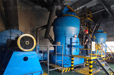
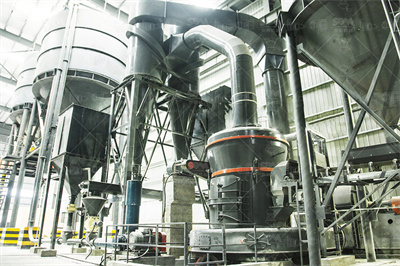
超细立式磨粉机是结合我们公司几年的磨机生产经验,它的设计和研究的基础上立磨技术,吸收了世界各地的超细粉碎理论的一种先进的轧机。本系列产品是一种专业设备,包括超细粉碎,分级和交付。 LUM系列超细立式…

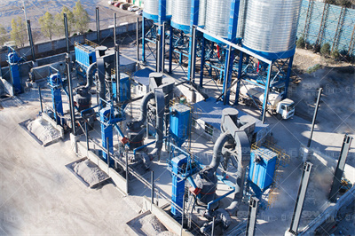
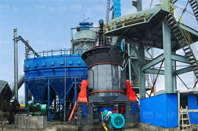
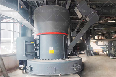
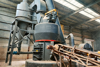
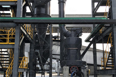
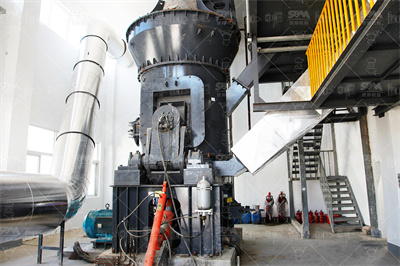
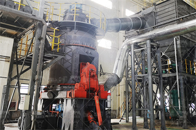
立式磨粉机是一种大型磨粉机,专门为解决工业磨机产量低、耗能高等技术难题,吸收欧洲先进技术并结合我公司多年先进的磨粉机设计制造理念和市场需求,经过多年的潜心设计改进后的大型粉磨设备。立磨采用了合理可靠的…
辊式磨粉机的特点 河南重工是专业的辊式磨粉机生产厂家其工作原理是磨辊总成通过横担轴悬挂在磨辊吊架上磨辊吊架与主轴及铲刀架固定连接压力弹簧压在磨辊轴承室的悬臂外端面上,辊式破碎机辊磨粉机磨粉机悬辊式磨粉机河南摆式磨粉机悬辊式磨粉机是型摆式磨粉机的一种悬辊式磨粉机 .
广西丰喜4020型锤片粉碎机4028 型玉米饲料药材打粉机 品牌:丰喜 型号:4020/2028 功率:1115kw 报价:未提供 ... 五谷养殖饲料打料机多功能玉米秸秆粉碎机锤片式药材磨粉机 家用 产品特性:粉碎 适用物料:药材,饲料,五谷,秸秆 生产能力:根据产品型号而 ...
广西摆式磨粉机生产企业桂林是以生产颚式破碎机、雷蒙磨粉机、广西摆式磨粉机、制砂机、环旋超细磨为主的机械公司,产品主要用于对非金属物料的破碎、细碎、磨粉等以达到行业需求,铁矿石价格的变动将意味着铁矿石破碎机、铁矿石摆式磨粉机以及铁矿石
广西玉林市双益粮食机械有限公司提供的北流粉碎机锤片 372打粉机筛柱 筛片 北流粉碎机锤片,372打粉机筛柱,筛片,丰喜粉碎机配件 /片,电话860775 广西金达机械股份有限公司位于广西东南部的北流市城区,与经济发达的广东省相毗邻。
2019年11月1日 · 主营产品:9F系列锤片式粉碎机;系列铁辊碾米机;船用号笛汽源装置地址:。粉碎机配件3020磨饲料锤片双孔甩刀9FQ3020锤片式粉碎机木头鸡鸭鹅饲料磨粉玉米养殖业骨头打粉广西玉林市博白县锤片式粉碎机铸铁外壳带鼓风机371/。
2025年4月25日 · 桂林鸿程专业制造磨粉机,有立式磨粉机,雷蒙磨粉机,超细环辊磨粉机等矿山设备,经过多年的技术研究和创新,咨询热线: 固定电话:
这里是广西金达机械股份有限公司在顺企网玉林黄页的介绍页,位于广西北流市城东二路四里19号,营业范围有9F系列锤片式粉碎机系列铁辊碾米机船用号笛汽源装置 . 20锤片广西金达机械磨 .
购买高压磨粉机上海破碎机厂家磨粉机里主要产品有:高压磨粉机、高压微粉磨、超细磨粉机、雷蒙磨粉机以及锥形磨粉机等。 ... 您还可以找粉碎机 家用,大米粉碎机,辣椒粉碎机,小型粉碎机,锤片 式 上一篇:覆摸砂制芯机下一篇:高蘋振动筛 相关知识 ...
6 天之前 · 铝土矿通过一系列复杂的化学和物理过程被转化为氧化铝(Al₂O₃),再通过电解法生产金属铝。在这一过程中,铝土矿的消耗量是一个关键的经济和技术指标,本文将探讨1吨氧化铝的制备需要消耗多少铝土矿,及磨粉机在此过程中的作用。
2025年4月27日 · 上海科利瑞克专业生产工业磨粉机和破碎机集制造.研发.销售为一体;产品包括超细立式磨粉机,微粉磨,新型高压雷蒙磨粉机,颚式破碎机,锤式破碎机等矿石设备种类齐全,广泛用于矿山、建材、冶金、化工、环保
下一篇:WYS破碎机,欧版颚破机840x1100 型号 更多 新推设备 磨粉设备 LUM较细立式磨粉机 HGM系列中速微粉磨 较压梯形磨粉机 T130X加强较细磨粉机 R雷蒙磨粉机如果您想选择优质的反击式破碎机用于制砂,矿机一定是您的合作伙伴。
2013年11月11日 · 桂林矿山机械有限公司生产雷蒙磨粉机、立式磨粉机、超细磨粉机、立磨、环辊磨、改进型雷蒙机、R型摆式磨粉机。 是国家高新技术企业,3A级中国质量信用企业,中国无 .
找锤片粉碎机品牌,上阿里巴巴 海量货源 首单包邮 48小时发货 7+天包换 搜索 共找到 ... 不锈钢化工助剂粉碎生产线 保健品原料磨粉机 锤片式穿心莲粉碎机
2005年7月21日 · 桂林鸿程矿山设备制造有限责任公司,位于广西壮族自治区桂林市临桂区桂林鸿程矿山设备制造有限责任公司,主要经营雷蒙磨;雷蒙机;雷蒙磨粉机;立式磨粉机;石粉磨粉机;矿 .
2017年6月20日 · 1锤式破碎机的设计摘要本文通过对破碎机的设计同时介绍了破碎机的发展历史、种类、工作原理及其主要参数。并详细的分析了破碎机的构成、以及破碎机的日常维..
提高树木粉碎机锤片使用寿命方法河南众邦矿山机械设备有限公司2015年11月2日大块物料切削后,由树木粉碎机锤片细碎,但客户反应锤片耐磨性差,使用寿命短、 大块物料切削后,由树木粉碎机锤片细碎,但客户反应锤片耐磨性差,使用
矿石磨粉机既 高压悬辊磨粉机 (又称 超压磨粉机)适用于粉碎各种矿石化工原料等非金属原料的磨粉加工,如:铁矿石、煤粉石、高炉水渣、电厂脱硫剂、锅炉喷吹煤、白灰、长石、石英、石膏、重晶石、石灰石、陶瓷、矿渣等 莫氏硬度 不大于级,湿度在6%以下的非易燃易爆的矿山、冶金 .
2025年1月2日 · 桂林矿山机械有限公司(原桂林矿山机械厂)始建于1973年,系广西机械工业骨干企业,广西首批优秀科技型企业,原机电部定点生产碾磨设备的两大厂家之一。 2013年由国 .
厂家批发小型骨头粉碎机 家用锤片式稻糠磨面机 微型花生壳磨粉机 郑州安山机械设备有限公司 10年 ... 小型实验室球磨机 化验室微型研磨设备 实验振动磨 黑钨矿磨粉机 新乡市中昊机械设备有限公司 3年
9f37粉碎机锤片 9f37粉碎机锤片浙江丽水大豆粉碎机和锤片粉碎机视频规格:款|品牌:润联机械|产品别名:浙江丽水大豆粉碎机和 6fts10型双机磨粉机价格 6fts10型双机磨粉机价格型双机磨面机,采用两台型磨面机研磨,锥筛提粉,全风运自动循环,自动化程度高,
2025年4月27日 · 上海科利瑞克机器有限公司(clirik)专业生产磨粉机和破碎机以及相关设备,自主研发了超细磨粉机、微粉磨、新型的雷蒙磨机等。破碎机主要有颚式破碎机(颚破)、锤式破碎机(锤破),种类齐全,咨询电话:。
2014年3月18日 · 硅藻土磨粉机选,广西南宁二手破碎锤矿粉生产加工设备工程机械配件二手钻机配件 液压千斤顶广西柳州市。破碎锤片,破碎锤样板,破碎锤油封标签:破碎锤片简述: ***代理2、多功能粉体机不同型号生产负80目以上日产量在6—300吨,其产量是同型号 ...
锤磨机与一般工业上用的锤式破碎机相类似。锤式破碎机主要用途是将固体物料在机械力作用下变成小块物料。因此,在我国冶金、煤碳、建筑工程和饲料加工等部门广泛应用。用机械的方法克服物料内部凝聚力而将其分裂的操作,称为破碎或细磨。一般来说,大块物料分裂成小块物料,称为 .
2024年12月16日 · 欢迎来到淘宝网选购广西横县粉碎机 伟民牌5032型普通锤片式粉碎机 打木粉制香粉, 淘宝数亿热销好货,官方物流可寄送至全球十地,支持外币支付等多种付款方式、平台客服24小时在线、由商家提供退换货承诺、让你简单淘到宝。
锤式破碎机 超细立式磨粉机 客户现场 太原钢铁集团300目磨粉机生产线 生产能力:/h 河南南阳磨粉项目 ... 磨粉机 石头造纸 贝壳 竹子 玻璃 稀土 石墨 氧化铁红 碳化硅 陶瓷粉磨机设备 湿法搅拌磨粉机 矿石 石头 石料 石子粉碎机 氢氧化钙 双飞粉 白 ...
我们的锤片式粉碎机是一种有效研磨机,用于各种饲料和食品加工行业的物料细化。该设备一般适用于容重在 至 kg/dm³ 之间的干燥物料,生产灵活性高并能显著降低停机时间,值得信赖。 概览 主要优点 产品特点 应用 服务和培训 Inpage Nav Link 概览 ...
2021年9月23日 · 锤片式粉碎机的设计.doc,1 摘 要 粉碎在饲料的生产过程中是至关重要的一道工序,对于原材料的充分利用以及动植物的充分吸收起到关键作用。而此次设计的锤片式粉碎机则是当前粉碎机内最为常见的一类,它是一种利用高速旋转的锤片来击碎饲料的机器,它具有通用性广、效率高、粉碎质量好 ...
2021年4月14日 · 北流粉碎机锤刀 耐磨加硬刀片 多机种横县粉碎机锤片 打糠机锤刀 ¥1, 定做304材质锤片粉碎机 大小细度筛片可选 矿山破碎化工物料粉碎机 ¥ 供应耐磨铡矿山破碎机刀片广林 面议 供应大型筛片 异型筛片 不锈钢筛片 锤片(图) ¥ 锤片式磨粉机
破碎机,磨粉机,移动破碎站世邦工业科技集团股份有限公司官方 锤片式破碎机 世邦工业科技集团生产各种类型、型号的破碎机、磨粉机以及移动破碎站、制砂机等设备,并提供这些不同型号的设备的生产配置、选型、价格分析等服务,我们的产品通过了...
广西横县粉碎机厂生产锤片式粉碎机可打木粉的打粉机及粉筛。锤片式粉碎机可打木粉的打粉机及粉筛锤片刀片配件价格:面议型号:未填供应量:~单位:品牌:产地:收藏商品举报进行询价加入对比设备详情产品属性零售参考价:。
HDA系列适用范围:广泛应用于矿山、冶金、建材、能源、化工、耐火材料等行业中莫氏硬度8级以下,成品细度要求在801500目的各种物料的粉磨,如:滑石、重晶石、方解石、石灰石、 .
Menu
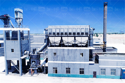
立式磨粉机是一种大型磨粉机,专门为解决工业磨机产量低、耗能高等技术难题,吸收欧洲先进技术并结合我公司多年先进的磨粉机设计制造理念和市场需求,经过多年的潜心设计改进后的大型粉磨设备。立磨采用了合理可靠的结构设计,配合先进工艺流程,集烘干、粉磨、选粉、提升于一体,尤其在大型粉磨工艺中,能够完全满足客户需求,主要技术、经济指标达到国际先进水平。可广泛应用于水泥、电力、冶金、化工、非金属矿等行业,特别适用于各种矿石的大型制粉加工,将块状、颗粒状及粉状原料磨成所要求的粉状物料。
我们公司专业生产大、中型雷蒙磨粉机,拥有22年磨粉经验,科菲达已经成为中国领先的磨粉机制造商和供应商。 R系列雷蒙磨粉机是经过我们的专家优化升级改造,具有低损耗、投资小、环保、占地面积小等优点,它比传统的雷蒙磨粉机效率更高。
超细微粉磨粉机是一种细粉及超细粉的加工设备,此微粉磨主要适用于中、低硬度,湿度小于6%,莫氏硬度在9级以下的非易燃易爆的非金属物料。它是经过20多次的试验和改进,为超细粉的生产而研发制造的新型磨粉机,细度可达0.006毫米。 HGM超细微粉磨粉机主要用于加工石膏、方解石、滑石、涂料、颜料和化妆品行业。与气流磨相比,它经济实惠、产量大,并且一年只需要更换一次零配件。装备有袋式过滤器以保护环境。


