超细微粉磨粉机
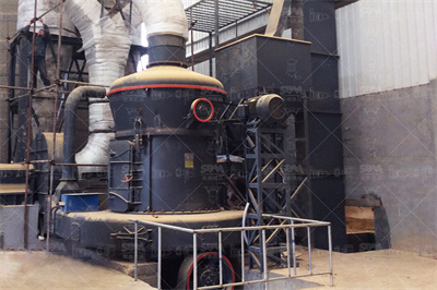
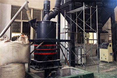
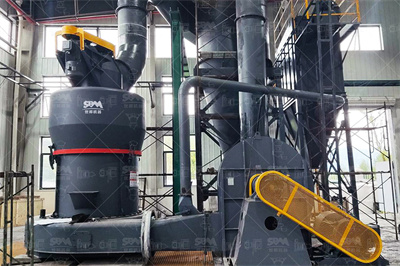
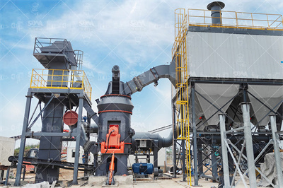
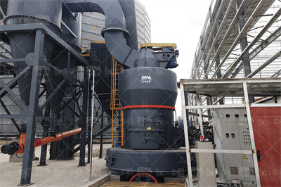
超细微粉磨粉机是一种细粉及超细粉的加工设备,此微粉磨主要适用于中、低硬度,湿度小于6%,莫氏硬度在9级以下的非易燃易爆的非金属物料。它是经过20多次的试验和改进,为超细粉的生产而研发制造的新型磨粉机,…
目录![]() +86 180 3780 8511We Hava More 35 Years Of Expeiences
+86 180 3780 8511We Hava More 35 Years Of Expeiences


超细微粉磨粉机是一种细粉及超细粉的加工设备,此微粉磨主要适用于中、低硬度,湿度小于6%,莫氏硬度在9级以下的非易燃易爆的非金属物料。它是经过20多次的试验和改进,为超细粉的生产而研发制造的新型磨粉机,…

我们公司专业生产大、中型雷蒙磨粉机,拥有22年磨粉经验,科菲达已经成为中国领先的磨粉机制造商和供应商。 R系列雷蒙磨粉机是经过我们的专家优化升级改造,具有低损耗、投资小、环保、占地面积小等优点,它比传…

MTW系列欧式磨粉机是我公司新近推出具有国际先进技术水平,拥有多项自主专利技术产权的最新粉磨设备—MTW系列欧式磨粉机,以悬辊磨粉机9518为基础,采用欧洲先进制造技术,它能满足客户对产品粒度、性能可…

获得了CE和国家专利证书,超压梯形磨粉机享誉澳大利亚、美国、英国、西班牙等客户国家。该机型采用了梯形工作面、柔性连接、磨辊联动增压等五项磨机专利技术,开创了超压梯形磨粉机的世界最高水平。TGM系列超压…

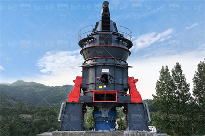
超细立式磨粉机是结合我们公司几年的磨机生产经验,它的设计和研究的基础上立磨技术,吸收了世界各地的超细粉碎理论的一种先进的轧机。本系列产品是一种专业设备,包括超细粉碎,分级和交付。 LUM系列超细立式…

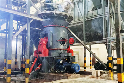
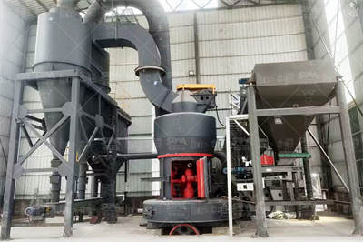
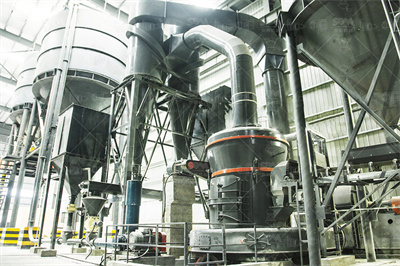
立式磨粉机是一种大型磨粉机,专门为解决工业磨机产量低、耗能高等技术难题,吸收欧洲先进技术并结合我公司多年先进的磨粉机设计制造理念和市场需求,经过多年的潜心设计改进后的大型粉磨设备。立磨采用了合理可靠的…
CPM HM系列锤片式粉碎机 HM系列锤片式粉碎机为最苛刻的工作环境而设计,是粉碎设备的最优解决方案。这种坚固的,高效的粉碎机采用了高密度的框架设计,其目的是为了最大程度的降 .
2018年5月14日 · 农机网为您推荐的产品垂片式饲料粉碎机是由湖南省湘粮机械制造有限公司提供,当前页面为垂片式饲料粉碎机的产品详细介绍页面,包含了垂片式饲料粉碎机产品的图片、 .
2013年7月9日 · 立轴式锤片粉碎机 在结构上的一项明显变革是其转子轴的立式布置。须粉碎的物料通过供料装置从机体上部的两个(或三个)进料口进入粉碎室,物料运动轨迹与锤片运动轨迹 .
Vertica 是一款有效的立式锤片式粉碎机,用于动物饲料生产、谷物和油类加工以及生物质行业中的研磨和预研磨。 双手安全机制可防止设备操作不当,保护操作员。您也可选择增加温度传感器 .
粉碎机配件:锤片 制粒机配件:抱箍 制粒机配件:安全销座总成 粉碎机配件:转子 制粒机配件:压辊轴 粉碎机配件:筛网 超微粉碎机配件:齿圈 制粒机配件:压模罩,切刀 粉碎机配件: .
2025年4月4日 · 垂片式粉碎机适用于制药、化工、食品等中低硬度物料的粉碎加工,细度在10120目之间调节,垂片式粉碎机具有产量高、粒度细、噪声低、能耗低、维修简单、安装方便 .
锤片式粉碎机是制药、食品、化工、科研、冶金等工业部门将含淀粉的物料或矿石;通过高速剪切、锤击在强气流的驱动下,经不锈钢筛网的过滤而得所需的粉剂,该设备设有吸尘装置,无粉末污染。 . 展开 本机采用冲击式粉碎方法,利用内部六只高速运转的活动锤体和四周固定齿圈的相对运动,使物料经锤齿冲撞、摩擦,彼此间冲击而获得粉碎。粉碎好的物料经旋转离心力作用,通过筛孔筛选后进入捕 . 展开
阿里巴巴热销400型垂片粉碎机树枝粉碎机设备秸秆稻草打糠饲料机一机多用,畜牧、养殖业机械,这里云集了众多的供应商,采购商,制造商。 这是热销400型垂片粉碎机树枝粉碎机设备秸 .
注:以上产量为在粉碎原料为经过粗粉后水分1518%以下的苜蓿草,粉碎机筛网孔径φ70mm 时的参考产量。 推荐产品 SFSP62×100×2木屑木块双转子粉碎机 SFSP68×168牧草草捆粉碎机 .
2014年6月6日 · 内容提示: 摘 要 本次毕业设计是完成小型锤片粉碎机的设计。 采用落料拉深、 胀形整形、 冲孔挤边工艺。 设计中分析了粉碎机的构造及工作过程、 粉碎机运动分析、 粉碎 .
阿里巴巴1688为您优选22条垂片式粉碎机热销货源,包括垂片式粉碎机厂家,品牌,高清大图,论坛热帖。 找,逛,买,挑垂片式粉碎机,品质爆款货源批发价,上1688垂片式粉碎机主题频道。
根据我国锤片式粉碎机正交设计试验结果,推荐谷物 R=4-8毫米,秸杆 R=10-14毫米。我国系列设计的锤片式粉碎机属通用型,一般 R=12毫米。9FQ60型粉碎机的 R=16毫米。FSP112×30 .
2025年3月26日 · 淘宝为你找到粉碎机垂片相关商品让你挑选,并提供了最新的折扣价格、详尽的产品规格参数、多样化的尺寸选项以及各相关品牌信息,助您以更优惠的价格选购到称心如意 .
SFSP系列水滴型锤片式粉碎机该系列粉碎机主要用于粉碎颗粒状物料,如:玉米、稻谷、谷壳等。它是理想的高效节能粉碎设备。主要技术参数型号规 .
2015年8月23日 · 摘要9F系列粉碎机中,9表示畜牧机械的分类代号,F指粉碎机,按其转子直径大小的不同可以分为:0、5、6、8、万能、多功能等型号,本人这次设计的是9F0型锤片式粉碎 .
FQ型FQ型垂片式饲料粉碎机参数FQ型FQ型垂片式饲料粉碎机参数及最新价格,公司客服电话7*24小时为您服务,售前/ 售后均可咨询 中国粉体网欢迎您! 登录 个人登录 企业登录 注册 .
JFS2000系列粉碎机江苏五龙机械有限公司用途和特点JFS2000系列水滴型锤片式粉碎机,采用"水滴型"机构,广泛适用于粉碎玉米、薯干、豆饼、高粱、大豆、贝壳及茎杆类原料,广泛应 .
锤片式粉碎机 专为满足高需求而打造。 苛刻的应用不会让我们感到困扰。这些坚固、高效的锤磨机提供尺寸和配置选项,以满足所有粒度减小需求,此外,它们还能够精细研磨易碎或纤维材 .
粉碎效率下降。剪式 锤片粉碎机 提高粉碎机效率的根本原理是增加粉碎机锤片 和物料的锤击速度差,而这一理念是许多专家和同行公认的。所以,提高粉碎机速度差一直也是人们所追求的。 .
锤式粉碎机的粉碎效果,主要是由粉碎细度、粉碎单位时间的产量和粉碎过程的单位能耗等3项指标来进行评定,这些指标取决于被粉碎物料的物理性能、粉碎机的结构、粉碎室的形状、锤片 .
2017年2月2日 · 锤片式粉碎机设计全解.doc,锤片式粉碎机设计 摘 要 饲料的粉碎在生产过程中是非常重要的一个程序。本次设计的锤片式粉碎机就是当前粉碎机中最为广泛的一种,它的原理是 .
2021年10月19日 · 美国锤片式粉碎机在安装、更换筛板时必须停机并且打开机壳才能进行,而欧洲的许多锤片式粉碎机是从轴向插入式,不需停机和打开机壳即可抽出原有筛板,插入新换筛板;还 .
2016年11月22日 · 粒度大小通过更换不同孔径的网筛获得。锤片粉碎机适应性较强,可一机多用。锤片粉碎机 构造简单,易于制造维修,造价便宜。2、齿爪式粉碎机对物料的粉碎以打击为 .
2020年3月3日 · 锤片式粉碎机设计摘要锤片式粉碎机是一种结构简单、通用性好、粉碎质量高的粉碎机械,目前广泛应用于国内外的各个行业,如制药业、食品加工业、饲料加工业等。粉碎机 .
2022年12月2日 · 本课题设计的是为一种小型的,经济型的粉碎机——9FZ37 型锤片粉碎机设计。 该机结构简单,使用方便,主要运用于粮食加工行业和食品加工行业,比较适合小型 作业的用 .
锤片粉碎机 转子上锤片的数量与排列方式,影响到转子的平衡、物料在粉碎室内的分布、锤片磨损的均匀程度以及粉碎机的工作效率。 锤片的数量用单位转子宽度上锤片的数量(锤片密度)来 .
Menu
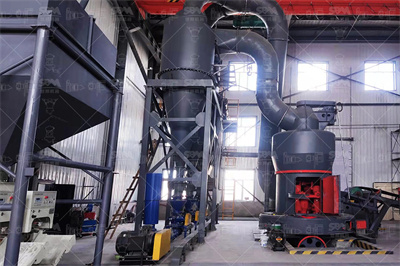
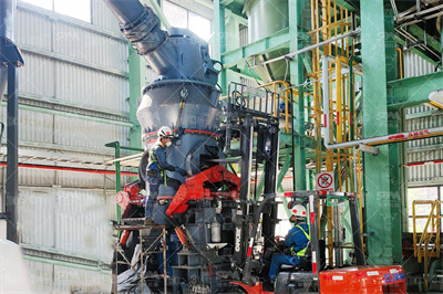
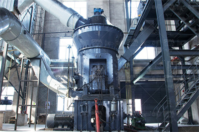
立式磨粉机是一种大型磨粉机,专门为解决工业磨机产量低、耗能高等技术难题,吸收欧洲先进技术并结合我公司多年先进的磨粉机设计制造理念和市场需求,经过多年的潜心设计改进后的大型粉磨设备。立磨采用了合理可靠的结构设计,配合先进工艺流程,集烘干、粉磨、选粉、提升于一体,尤其在大型粉磨工艺中,能够完全满足客户需求,主要技术、经济指标达到国际先进水平。可广泛应用于水泥、电力、冶金、化工、非金属矿等行业,特别适用于各种矿石的大型制粉加工,将块状、颗粒状及粉状原料磨成所要求的粉状物料。
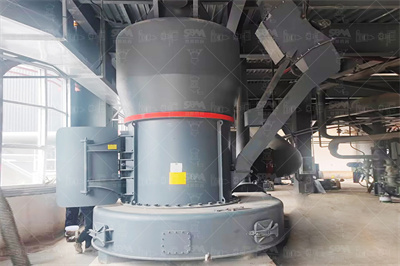
我们公司专业生产大、中型雷蒙磨粉机,拥有22年磨粉经验,科菲达已经成为中国领先的磨粉机制造商和供应商。 R系列雷蒙磨粉机是经过我们的专家优化升级改造,具有低损耗、投资小、环保、占地面积小等优点,它比传统的雷蒙磨粉机效率更高。
超细微粉磨粉机是一种细粉及超细粉的加工设备,此微粉磨主要适用于中、低硬度,湿度小于6%,莫氏硬度在9级以下的非易燃易爆的非金属物料。它是经过20多次的试验和改进,为超细粉的生产而研发制造的新型磨粉机,细度可达0.006毫米。 HGM超细微粉磨粉机主要用于加工石膏、方解石、滑石、涂料、颜料和化妆品行业。与气流磨相比,它经济实惠、产量大,并且一年只需要更换一次零配件。装备有袋式过滤器以保护环境。


